

Crystal Instruments EDM Remote Condition Monitoring (RCM) Software
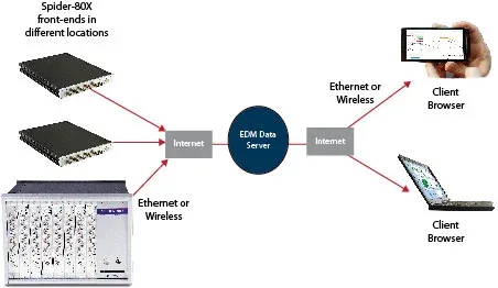
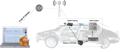
Connects Spider front-ends anywhere in the world through cellular networks, and…
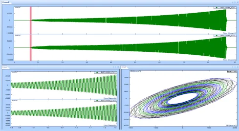
Two orthogonal time-domain signals plot the shaft centreline as a 2D orbit, exposing imbalance, oil whirl and misalignment.
Made by Crystal Instruments Corporation. Supplied and supported in China by WTC (West Technology Corporation). · Manufacturer page ↗
The Orbit Plot is a time-domain display tool for rotating machinery diagnostics. It draws the signals from two time-domain channels on an X and Y plane, showing how the shaft position changes against the angle of rotation and giving a two-dimensional picture of the motion of a rotating shaft.
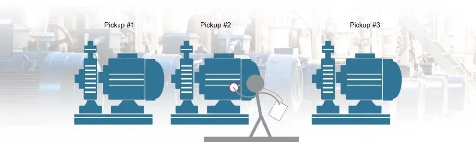
Building an orbit plot requires a dual-channel simultaneous measurement: data must be captured on the horizontal and vertical axes at the same time, with the displacement or acceleration sensors placed 90 degrees apart. The display format is similar to a polar plot, but it is constructed from two mutually perpendicular signals and is typically associated with the current rotating speed of the shaft. Unlike order tracking, an orbit plot does not require order normalization, which keeps field acquisition and interpretation straightforward.
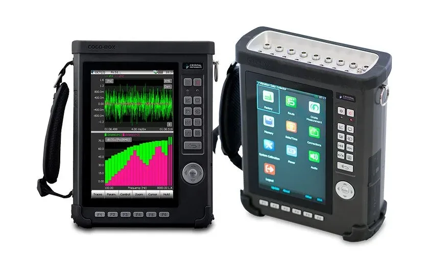
The shape of the orbit is itself diagnostic information. A well balanced shaft with no movement in any direction produces a single dot at the centre of the plot. Pronounced up-and-down movement may indicate that the machine feet are not bolted down tightly enough. Other orbit shapes help identify imbalance, misalignment, dry rub and oil whirl. Orbit plots are commonly used together with run-up and coast-down waterfalls and order tracking to carry out on-site rotating machinery diagnostics on the CoCo-80X handheld analyzer and the Spider platform.
This entry describes a solution or service without fixed hardware specifications. Contact us for a configuration.
Tell us the test object and the standard you must meet. An engineer replies within one business day.
Connects Spider front-ends anywhere in the world through cellular networks, and…
Vibration data management and automated diagnostics for predictive maintenance…
Route-based vibration collection with the CoCo handheld analyzer and EDM softwa…
Send us the test object, the standard and your lab conditions. You get a configuration list within one business day.