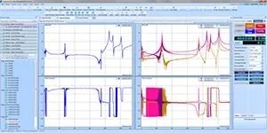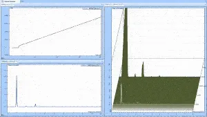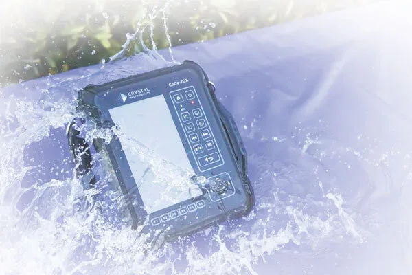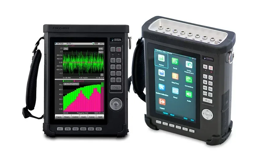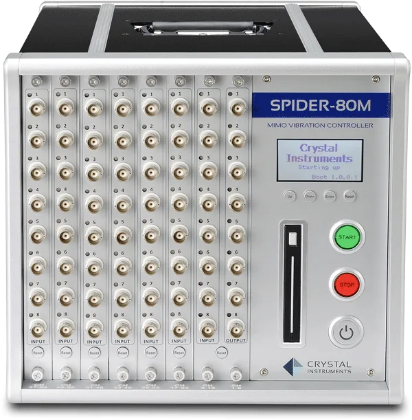


Crystal Instruments Acoustic Analysis Software
Real-time fractional-octave and sound level meter analysis from 1/1 to 1/12 oct…
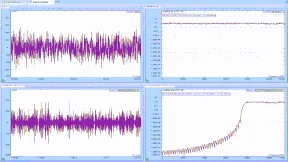
FIR, IIR and decimation filters running in real time on the front-end, designed graphically as a dB response curve to isolate any frequency band.
Made by Crystal Instruments Corporation. Supplied and supported in China by WTC (West Technology Corporation). · Manufacturer page ↗
Real-Time Digital Filters filter a measured signal on the fly, with characteristics defined by the user to meet a specific application. They are applied in the data-conditioning phase: the filter is designed with a graphic tool and then uploaded to the front-end for real-time calculation. The design tool plots filter performance on a dB vertical axis against relative frequency on the horizontal axis.
A typical use is to view the energy in a narrow band over time rather than the whole spectrum: create a band-pass filter and apply an RMS estimator to its output. In EDM this is drawn as a graphical block diagram, connecting the native measured time stream CH1 to an IIR filter and then to an RMS estimator to produce a signal such as rms(iirfilter(ch1)).
The option includes three filter types: Finite Impulse Response (FIR), Infinite Impulse Response (IIR) and decimation filters. For FIR and IIR, low-pass, high-pass, band-pass or band-stop filters can be specified with several design methods. Filter design calculates a series of coefficients from user criteria described by: the number of coefficients (filter order, where a lower order responds faster with less input-to-output lag); cutoff frequencies (one for low/high-pass, two for band-pass/band-stop, e.g. about 0.1 and 0.2 Hz); stop-band attenuation (how strongly rejected frequencies are cut, ideally high, with the example reaching more than 40 dB); pass-band ripple (which should be minimal for a flat pass-band while some stop-band ripple is tolerable); and transition-band width (ideally narrow, though a very narrow transition requires a higher-order filter that affects response time and ripple).
In most cases filter design trades off filter order, ripple, transition bandwidth and response time, which cannot all be optimized at once, so the process is often iterative and benefits from experience.
This entry describes a solution or service without fixed hardware specifications. Contact us for a configuration.
Tell us the test object and the standard you must meet. An engineer replies within one business day.
Real-time fractional-octave and sound level meter analysis from 1/1 to 1/12 oct…
A free ATFX reading API — two Windows DLLs that let C#, Python, Matlab and LabV…
Three FRF methods in one package: FFT, swept sine and multi-resolution spectrum…
Speed-referenced order-domain analysis with dual tachometer inputs and up to 12…
Send us the test object, the standard and your lab conditions. You get a configuration list within one business day.