

Crystal Instruments Acoustic Analysis Software
Real-time fractional-octave and sound level meter analysis from 1/1 to 1/12 oct…
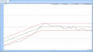
Computes a shock pulse's damage potential via a bank of SDOF filters, with 1/1 to 1/48 octave spacing, three spectrum types and four synthesis methods.
Made by Crystal Instruments Corporation. Supplied and supported in China by WTC (West Technology Corporation). · Manufacturer page ↗
A Shock Response Spectrum (SRS) graphically presents a transient acceleration pulse's potential to damage a structure. It plots the peak acceleration responses of a bank of single degree-of-freedom (SDOF) spring-mass-damper systems, all experiencing the same base excitation as if on a rigid massless base. Each system has a different natural frequency and the same damping factor; plotting peak accelerations vertically against natural frequencies horizontally yields the spectrum. The process is: specify a damping ratio (5% is common), model an SDOF of frequency fn and damping xi with a digital filter, apply the transient and compute the response acceleration, retain the peak positive and negative responses during and after the pulse, select one extreme as the spectrum amplitude at fn, and repeat for each logarithmically spaced fn.
An SDOF system of mass, spring and damper is characterized by its natural frequency Fn and critical damping factor xi. For light damping (xi <= 0.05) the peak response occurs near fn and the quality factor Q equals 1/(2 xi), so 5% damping gives Q = 10. Any transient can be presented as an SRS, but the relationship is not unique; damping changes the spectrum, with zero damping giving the maximum response and high damping a flatter curve. An SRS plot is incomplete unless it states the damping factor or Q.
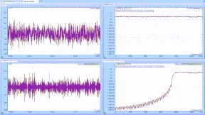
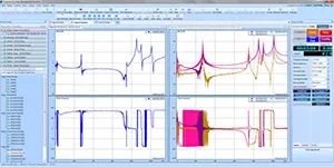
SRS bins are evenly distributed on a logarithmic frequency scale, defined by a reference frequency and a fractional octave spacing such as 1/1, 1/3 or 1/6, where 1/N means N band-pass filters per octave. The Spider SRS test measures each channel's time stream (raw data), block-captured time signals and three SRSs: Maximum Positive, Maximum Negative and Maximax (the envelope of absolute values and the most widely used, usually shown in log-log form). Analysis parameters include reference frequency, SRS type, fractional octave number (1/1 to 1/48), low and high frequency, damping ratio, Q, and a wavelet window (Sine, Hann, Exponential, Rectangular). Four synthesis methods are available: Pyroshock, Minimum Acceleration, user-defined duration and Mil-Std-810F.
This entry describes a solution or service without fixed hardware specifications. Contact us for a configuration.
Tell us the test object and the standard you must meet. An engineer replies within one business day.
Real-time fractional-octave and sound level meter analysis from 1/1 to 1/12 oct…
A free ATFX reading API — two Windows DLLs that let C#, Python, Matlab and LabV…
FIR, IIR and decimation filters running in real time on the front-end, designed…
Three FRF methods in one package: FFT, swept sine and multi-resolution spectrum…
Send us the test object, the standard and your lab conditions. You get a configuration list within one business day.